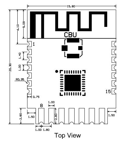
| Pin number | Symbol | I/O type | Function |
1 | P14 | I/O | Common GPIO, which can be reused as SPI_SCK (Correspond to Pin 11 of the IC) | 2 | P16 | I/O | Common GPIO, which can be reused as SPI_MOSI (Correspond to Pin 12 of the IC) | 3 | P20 | I/O | Common GPIO (Correspond to Pin 20 of the IC) | 4 | P22 | I/O | Common GPIO (Correspond to Pin 18 of the IC) | 5 | ADC | I/O | ADC, which corresponds to P23 on the internal IC (Correspond to Pin 17 of the IC) | 6 | RX2 | I/O | UART_RX2, which corresponds to P1 on the internal IC. (Correspond to Pin 28 of the IC) | 7 | TX2 | I/O | UART_TX2, which is used for outputting logs and corresponds to P0 of the internal IC (Correspond to Pin 29 of the IC) | 8 | P8 | I/O | Support hardware PWM (Correspond to Pin 24 of the IC) | 9 | P7 | I/O | Support hardware PWM (Correspond to Pin 23 of the IC) | 10 | P6 | I/O | Support hardware PWM (Correspond to Pin 22 of the IC) | 11 | P26 | I/O | Support hardware PWM (Correspond to Pin 15 of the IC) | 12 | P24 | I/O | Support hardware PWM (Correspond to Pin 16 of the IC) | 13 | GND | P | Power supply reference ground | 14 | 3V3 | P | Power supply 3V3 | 15 | TX1 | I/O | UART_TX1, which is used for transmitting user data and corresponds to Pin 27 of the IC. For the MCU solution, please refer to CBx Module. | 16 | RX1 | I/O | UART_RX1, which is used for receiving user data and corresponds to Pin 26 of the IC. For the MCU solution, please refer to CBx Module. | 17 | P28 | I/O | Common GPIO (Correspond to Pin 10 of the IC) | 18 | CEN | I/O | Reset pin, low active (internally pulled high), compatible with other modules (Correspond to Pin 21 of the IC) | 19 | P9 | I/O | Common GPIO (Correspond to Pin 25 of the IC) | 20 | P17 | I/O | Common GPIO, which can be reused as SPI_MISO (Correspond to Pin 14 of the IC) | 21 | P15 | I/O | Common GPIO, which can be reused as SPI_CS (Correspond to Pin 13 of the IC) | Test point | CSN | I/O | Mode selection pin. If it is connected to the ground before being powered on, enter the firmware test mode. If it is not connected or connected to VCC before being powered on, enter the firmware application mode. Correspond to Pin 19 on the internal IC. |


